Major Fail !
I’m really at a loss for words on this one. All I can say is this was installed by a journeyman plumber.
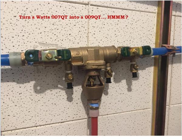 Photo provided by my good friend and colleague Dave over at A+ Backflow.
Improper Startup of a Backflow Assembly
Manufactures provide pressurization startup procedures for newly installed or repaired backflow prevention assemblies. Failure to read the instructions provided by the manufacturer can result in problems like the one you see here.
As you can see in the 1st photo check valve number 1 is jammed open. This is caused when a contractor does not follow procedure. They opened shut off valve number 2 first and then they opened shut off valve number 1 way too fast.
Typical startup procedures are as follows: With both shut off valves in the closed position, 1st slowly open shut off valve #1, use the test Cocks to bleed the air out of the assembly, then simply slowly open shut off valve #2.

The picture below shows how the check valve should look in a no flow static condition.

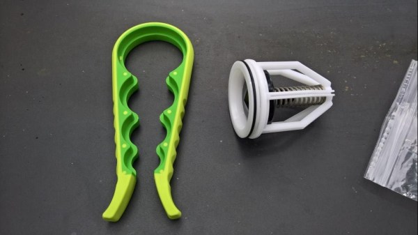
What Jar Opener?
Everybody’s been asking me what jar opener? So I decided to throw a couple of pictures up to clear the air. The dark green section is of a soft rubbery compound which will not damage your check module or O ring, yet with little pressure the module will not slip.
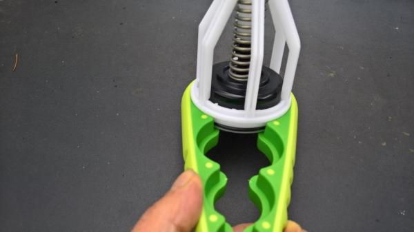

Experience has taught me that rubber kits are a waste of time and money when repairing module type check valves with plastic seats. The assembly may pass after the installation of a rubber kit, but it rarely brings the assembly back up to factory specifications that are shown on the manufacturers flowchart. For this reason 98% of the time I replace the entire module. However there are times when there’s absolutely nothing wrong with the module except for it needing a cleaning and a thorough inspection, this is where this simple homemade tool comes in handy.
I’m only in my 50s but I rarely have been able to get the 1.25” and larger 009 #1 check module apart, and when I have I was not able to get it back together. So I used items around the house to make a tool that makes this a simple process that I will be able to do when I’m in my 70s.

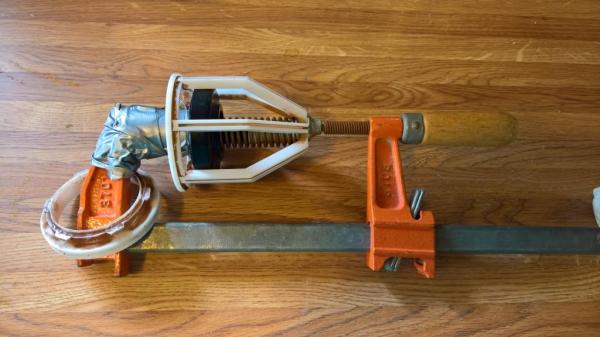
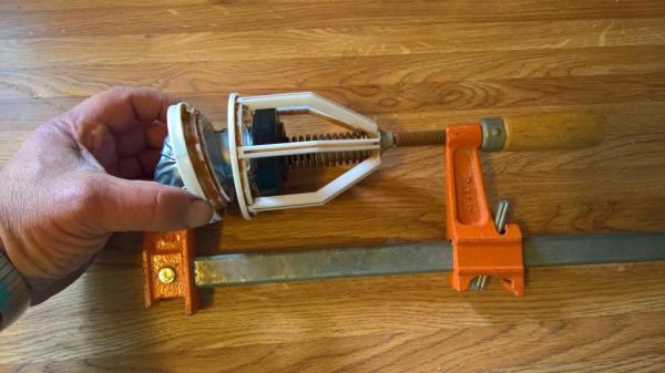
 It’s simply a socket taped to a clamp.
Just put a couple drops of food grade lubricant on the area of the cage that the seat locks into and use a jar opener to twist and lock the seat into place. You can quickly clean and inspect the seat, poppet, disc, etc.
Remember a proper repair will bring the assembly up to factory specifications. If your repair only makes the assembly barely pass the minimum guidelines it is not a proper repair and you should rebuild it again until you get it right. Every now and again you’re going to get an assembly that’s going to kick your butt. Just stay calm and stick with it and through perseverance you will get it right.
The 1st Step to Backflow Assembly Repair
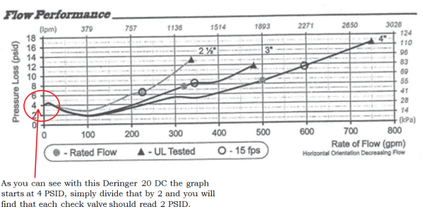
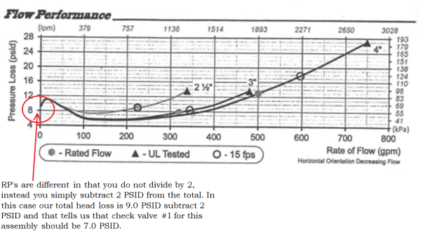
Before a backflow assembly can be repaired to factory specifications the technician must refer to the manufactures supplied flowchart. The flowchart tells us what the factory specification “PSID” should be for each check valve.
For instance if you repair the check valve in a DCVA and you get a reading of 1.1 PSID after your repair but the flowchart indicates the PSID for the check valve should be 2.6 PSID then you have not properly repaired the assembly.
It’s also important to note the only time you should check “LEAKS” on your test report for a DCVA is if you’re gauge PSID reading is “0.0”. If your gauge reads 0.1 PSID the check valve is still holding “TIGHT” and you should check the “TIGHT” box and record your findings.
“LEAKS” should only be checked when you get a 0.0 PSID reading. All other readings should be marked “TIGHT” for DCVA’s / DCDA’s, PVBA’s & SVBA’s. “LEAKS” should only be used on RPBA’s if after your testing / diagnostics you discover one of the check valves are failing causing the relief valve to vent.
In Honor of a Dear Friend, Brother, and Colleague; Steve Nelson of Veteran Backflow Service
Beloved son, brother, uncle, and friend, Stephen Trent Nelson entered into rest on December 30, 2017 after a prolonged illness from cancer. Stephen was the first son born to Major Clayton Jack and Mary Mae Reynolds Nelson on May 20, 1951 in Munich, Germany. As a young child, he lived in Newfoundland and Illinois, and later settled with his family in the Lake City suburb of Tacoma, WA. Steve graduated from Lakes High School in 1969.

At age 19, Stephen joined the U.S. Army and was soon deployed to Vietnam where he served October 5, 1970 to December 4, 1971. During his time there, Steve was a journalist assigned to the Delta Dragons, Military Assistance Command Vietnam (MACV) Team 96 in Can Tho, Mekong Delta. He rode helicopters all over South Vietnam to investigate stories and wrote articles published in his unit’s newspaper as well as the Stars and Stripes. He was proud and honored to have served his country, like his father and uncles before him.
Although he was a lifelong resident of Washington, Steve traveled throughout the United States upon his honorable discharge in the ‘70s. He hitchhiked cross-country twice, with extended stays in South Carolina and Florida.


For the past several decades, Stephen was the property superintendent for companies in Seattle, Everett, SeaTac and Burien. Since 2011, Steve ran his own successful business, Veteran Backflow Services. He truly loved this job and the camaraderie he found with other entrepreneurs in the industry.
Steve was an avid sports fan, rooting for the Mariners, the Seahawks, the Packers, and the Sonics. He also loved music of all kinds, especially the Beatles. A voracious reader, his home was filled with books of all genres. He had an eye for art, a green thumb, and a loving heart. Stephen will be missed for his many kindnesses, quick smile, and true compassion for others.
What causes a relief valve to open up early? “5.0 PSID or above”
Technically when a relief valves opening point is above 5.0 PSID it is considered a failure and the relief valve should be repaired.
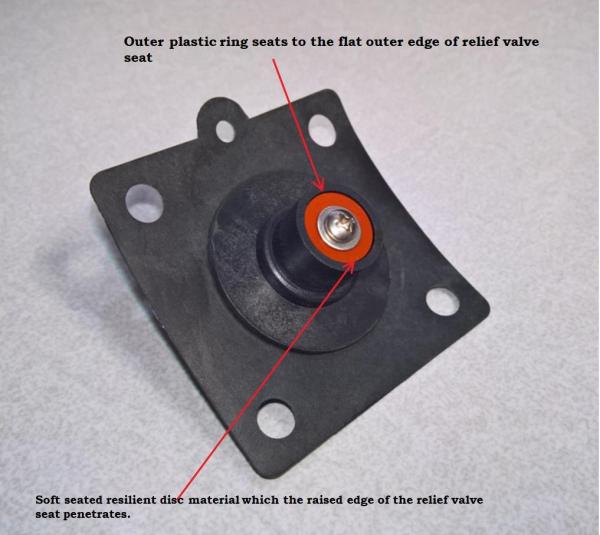
The relief valve is a resilient soft seated design. In the example photo above, the relief valve disc is mounted in the relief valve assembly so it is flush to the hard plastic outer ring. This hard plastic outer ring is designed to seat on the outer flat edge of the relief valve seat, there by the raised inside sharp edge of the seat only penetrates into the soft resilient disc material specified by engineering specifications. “If the relief valve on the assembly you’re testing opens up early it is because the relief valve is not seating 100% per specifications on the relief valve seat.”
For example if the relief valve seat is supposed to penetrate the relief valve disc by 30% but the relief valve seat is only partially penetrating the disc by 5%, the movement the relief valve must move before the relief valve begins to vent water is reduced by 25%, i.e. the relief valve opening early or at an excessively high PSID.
In short, regardless of the design; if your relief valve is opening above 5.0 PSID then it is safe to assume that your relief valve is not seating 100% and therefore is not working properly. To avoid property damage and a possible emergency repair this should be addressed at the time of service.
Dry Fire Systems & Backflow Prevention Testing
When testing a backflow prevention assembly with OSY or NRS valves on a dry fire sprinkler system the simple act of closing shut off valve #2 can build up enough pressure on the upstream side of the Clapper valve to trip the system. It happens to many backflow testers every single year, it has never happened to me because I follow these simple steps.

- In the photo there are 2 gauges, the lower gauge is the water pressure on the upstream side of the Clapper valve. The upper gauge is the air pressure on the downstream side of the Clapper valve. The air pressure is what keeps the Clapper valve closed. There are many different dry systems on the market and some systems require more air pressure than others. If the readings are equal to the values below you are in little to no danger of tripping the clapper valve when testing the backflow prevention assembly.
- Water PSI = Air PSI
60-80 PSI = 30-35 PSI
80-100 PSI = 35-40 PSI
100-120 PSI = 40-45 PSI
120-140 PSI = 45-50 PSI
If your air pressure is lower than what is indicated on the above chart for a given water pressure that “may” indicate a problem and you should inform your customer and make it clear you are not certified in dry systems and it would be wise to have a certified technician inspect it.
- As you’re slowly closing shut off valve #2 on the backflow preventer keep an eye on the lower water pressure gauge on the dry system. If the needle begins to rise STOP what you’re doing and slightly open test cock #4. The water pressure gauge on your dry system should drop back down to the original reading. Continue to slowly close shut off valve #2 while continuing to watch the gauge; the water pressure should remain stable. Once you have the shut off valve closed tight you can close test cock #4 and begin your test.
- If the air pressure is much lower than the chart above for a given water pressure your best option is not to touch the assembly until the dry system has been checked out by a certified technician.
- Remember it is extremely important to know what the downstream process is before you shut the water off. It’s up to you to educate yourself on the various types of systems to avoid costly damages to the equipment downstream of the assembly.
The No Good, Bad & the Ugly
“Here is an improper installation with multiple deficiencies.”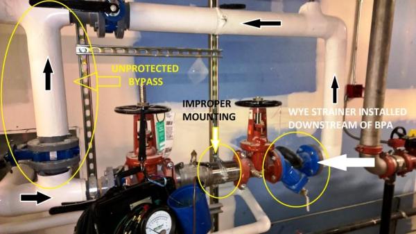
1) System has an unprotected bypass, this is not allowed.
2) Backflow assembly is not mounted per manufactures written specifications; mounting bracket blocks the ability to repair this assembly.
3) The Wye strainer is installed downstream of the backflow preventer. In order for the Wye strainer to perform its job and prevent debris from impeding check valve operation it must be installed upstream of the backflow preventer per manufacturer’s written instructions.
4) Both check valves leaked on this DCVA because the internal assembly was filled with gravel, the contractor did not follow manufacturers written installation instructions and flush the lines before installing the backflow preventer.
It’s important to note: if the Wye strainer was properly installed upstream of the backflow preventer per manufacturer’s suggestion, it would have blocked the gravel from entering the assembly and jamming the check valves in the fully open position consequently leaving the city water supply unprotected.
Below is off of Watts basic installation instructions found on the 774 series:
Check with local authorities for installation requirements. Install valve in the line with arrow on valve body pointing in the direction of flow. Pipe lines should be thoroughly flushed to remove foreign material before installing the unit. A strainer should be installed ahead of the backflow preventer to prevent discs from unnecessary fouling.
CAUTION: Do not install a strainer when a backflow preventer is used on seldom-used water lines which are called upon during emergencies, such as fire sprinkler lines, etc.
Notify, Identify, Inspect and Observe
This is an example of why it’s very important to “IDENTIFY” and “INSPECT” every assembly.
I sent an unmarked copy of this photo to several colleagues of mine and I asked them what they saw. They all assumed the last backflow tester failed to restore service to this existing assembly on a residential fire sprinkler system.
The problem is they are only looking at the backflow shut off valves #1 & #2. They failed to see that the fire sprinklers “Inspectors test/drain valve is in the open position,” and the “sprinkler system pressure gauge shows 0 psi.”
I do not know why the backflow assembly shut off valves are in the closed position and the inspector test valve is in the open position on this occupied residential property. What I do know is, if I restore service to this fire sprinkler system I will cause the alarm to sound and may cause property damage.
All I can do is return the system to the way I found it after I completed the test, then notify the owner of the situation, as well as inform the water department using the comments section on my test report.
Remember your USC training: NOTIFY, IDENTIFY, INSPECT, and OBSERVE.