A Frankenstein Backflow Assembly


Pics 1 through 3:
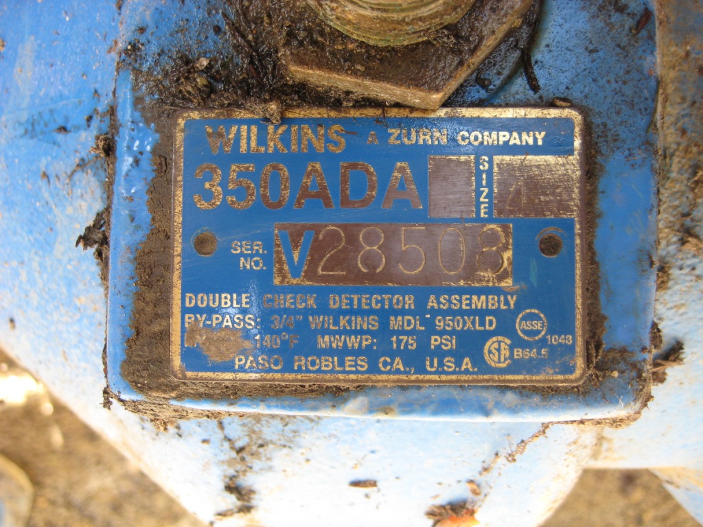
Here’s one for the good bad and the ugly. This is a 350ADA which the installer had converted to a Frankenstein RPBA/DCDA? I don’t know what you’d call this thing.
It was installed in 2013 and the CCS at the water district inspected the assembly at that time, but because the vault is small the relief valve went unnoticed.
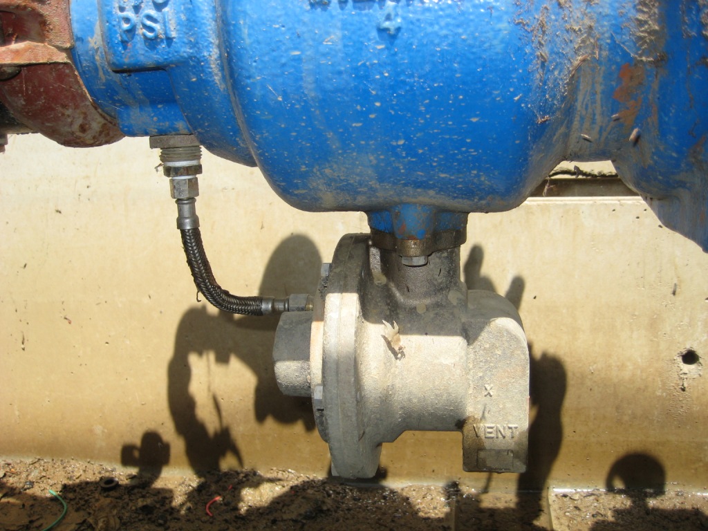
The 1st tester tested it is a double check and got acceptable values in 2013. In 2014 I tested it as a double check and got good values. This year I go to test the assembly and suddenly my feet get soaked. I bend down and discovered the relief valve. The relief valve must have been stuck closed for the 1st two testing sessions.
I immediately put the system back online and went to see the CCS at the water Department. I explained what had happened and he was pretty surprised as he also initially inspected the assembly. I asked him if I can legally return the assembly to factory specifications? Because it still had the factory DC check modules installed it would only require a bulkhead assembly, cover plate, etc. Of course the CCS told me that it did have to go back to factory specifications.
Bottom pic:
I wanted to know why the relief valve did not vent for two different testers with 2 different companies for the 1st two years.
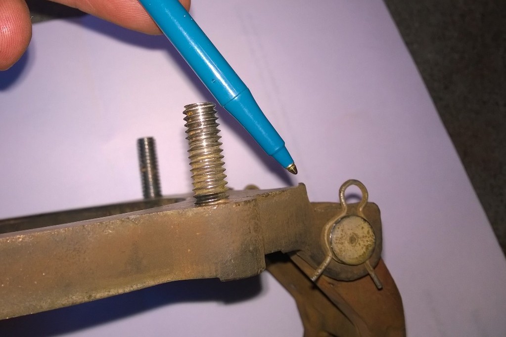
Turns out someone had stuffed paper in the relief valve stem to keep it forced closed. Over time the paper must have compress and degraded, this explains why the relief valve did not dump normally when it finally did open. Obviously it could not open fully.
Click on photos to enlarge
Irrigation Reduced Pressure Backflow Assembly
 I have just restored service for this improperly installed irrigation backflow assembly. This is a 1″ Wilkins 975XL RPBA which is installed below ground with no daylight drain. When this backflow assembly fails the box may fill with water and create a potential indirect crossconnection.
As a backflow assembly tester it is important to note this on your test report to relieve yourself of any liability. Click photo to enlarge
Improper New Installations
 The photo on the right is a good example of some of the improper new installations we run across from time to time.
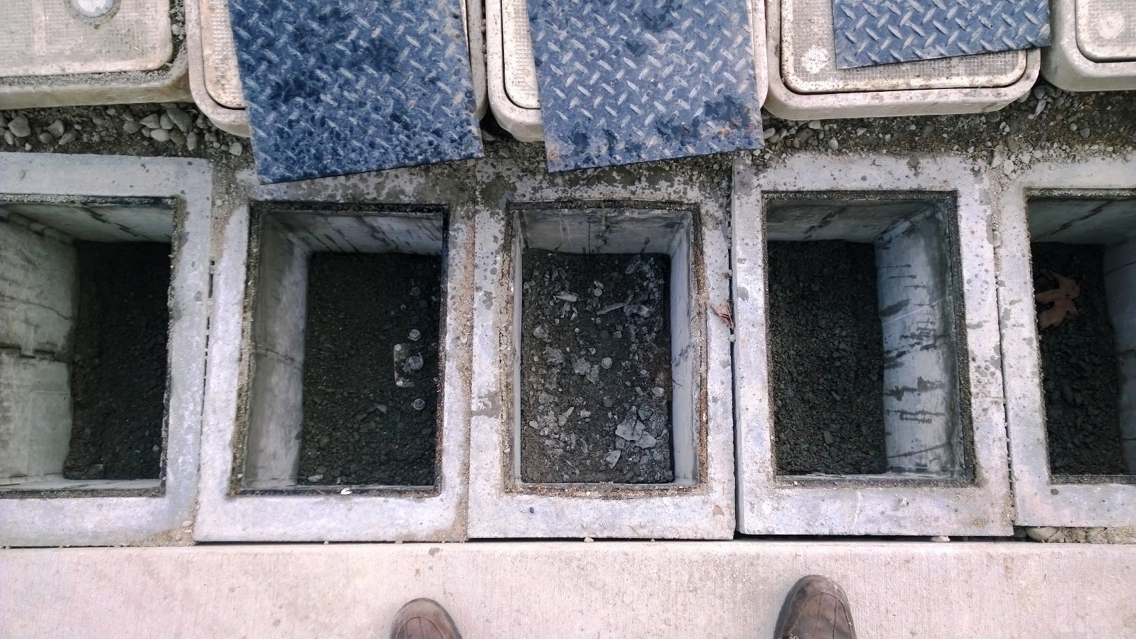
Backflow preventer’s are required t0 have 12″ of clearance below the assembly. These look like they were installed then covered up with dirt to set the boxes.
4” Ames 2000SS Check Valve Failure
 This is a Cam Check out of a 4″ Ames 2000SS, the area circled in yellow is typical of what you will find when these assemblies fail.
These rubber parts are not replaceable and this cam check had to be replaced.
click on photo to enlarge
Unapproved Backflow Assembly Modification
 Photo compliments of Redwood Backflow, Redmond Washington.
This is an unapproved modification to a backflow assembly for a commercial tanker fill station.
The equipment circled in this photograph should have been installed downstream of shutoff valve #2 where the arrow is pointing. Currently the device is installed between test cock #3 and test cock #4.
This backflow assembly failed the backflow test; however there is no way of knowing if this assembly is failing because of a bad check valve, or as a result of the unapproved improper installation. The backflow assembly should be disassembled and reassembled properly before an accurate backflow test can be made.
As a certified backflow assembly tester you must mark this as an improper installation and explain why in the remarks section on your test report. You are required to “inspect” as well as “test” the assembly. Your test report is a legal document, when filled out properly it will protect you from liability.
Factory Defective Backflow Assemblies
 The ballpoint pen in this picture is pointing at a casting defect on the bottom of a 4″Febco 870 seat.
This defect is prohibiting the seat from coming into full contact with the seat gasket and the assembly to provide a watertight seal.
When inspecting parts during a repair, it is important to take the time to inspect the entire part not just one side for damage, manufacturing defects, etc.
Click photo to enlarge
Backyard Backflow Assembly Mechanic
 This is a 1″ Watts 009M2QT relief valve. It was tested by a certified backflow tester when it was installed and it passed the initial test.
Some time after that and prior to the home being sold the assembly began to vent water. Most likely the builder, in his infinite wisdom, had a carpenter fix it. The odds are the technician damaged the piston O-ring upon reassembly causing water to flow through the relief valve stem vent. The technician rectified the problem by plugging the relief valve stem vent with a screw. The technician also failed to reinstall the relief valve spring. As a result he succeeded in making sure the relief valve would never open again.
This is just one reason why we test the backflow assemblies annually. Aside from failures due to normal wear and tear, there are folks out there who think they are doing the right thing by modifying an assembly in an attempt to repair it. These modifications reduced a high hazard protection backflow assembly, to a low hazard device, and of course this is not allowed.
Mixed Up Backflow Detector Assembly

This is a new installation of an 8” Colt 300BF with a ¾” Ames 2000BM3 detector assembly.
If you look closely you will see the upstream side of the ¾” Ames 2000BM3 is connected to shut off valve #2, and the downstream side is connected to shut off valve #1. The detector meter itself is connected correctly with the direction of flow arrow pointing up. However with the way this is set up the detector meter can only run backwards.
This is an improper installation which has created an unprotected cross connection.
Click photo to enlarge
.
Obsolete Backflow Prevention Assembly

Here we have a very old 3” Beeco C6 Reduced Pressure Backflow Assembly on a domestic water line. Everything is still working like new, the test values are very very good and the shut off valves still close tight.
All this and this backflow assembly is on a cast iron plumbing system. It would not surprise me if this backflow preventer lasted another 10+ years.
Febco Model 850 Double Failure

Febco 850/860 Backflow Prevention Assembly Disk Retainer Screws
Here we have a 1.5” Febco 850 as you can see the disk retainer screws for both checks have come loose and flowed downstream.
I am told the cone shaped object circled in yellow is a fix Febco designed that goes in front of the model 850/860 first check module. Its purpose is to help reduce the vibration that causes the disk retainer screws to come loose.
Click to Enlarge